Add a controlled interface at each phase
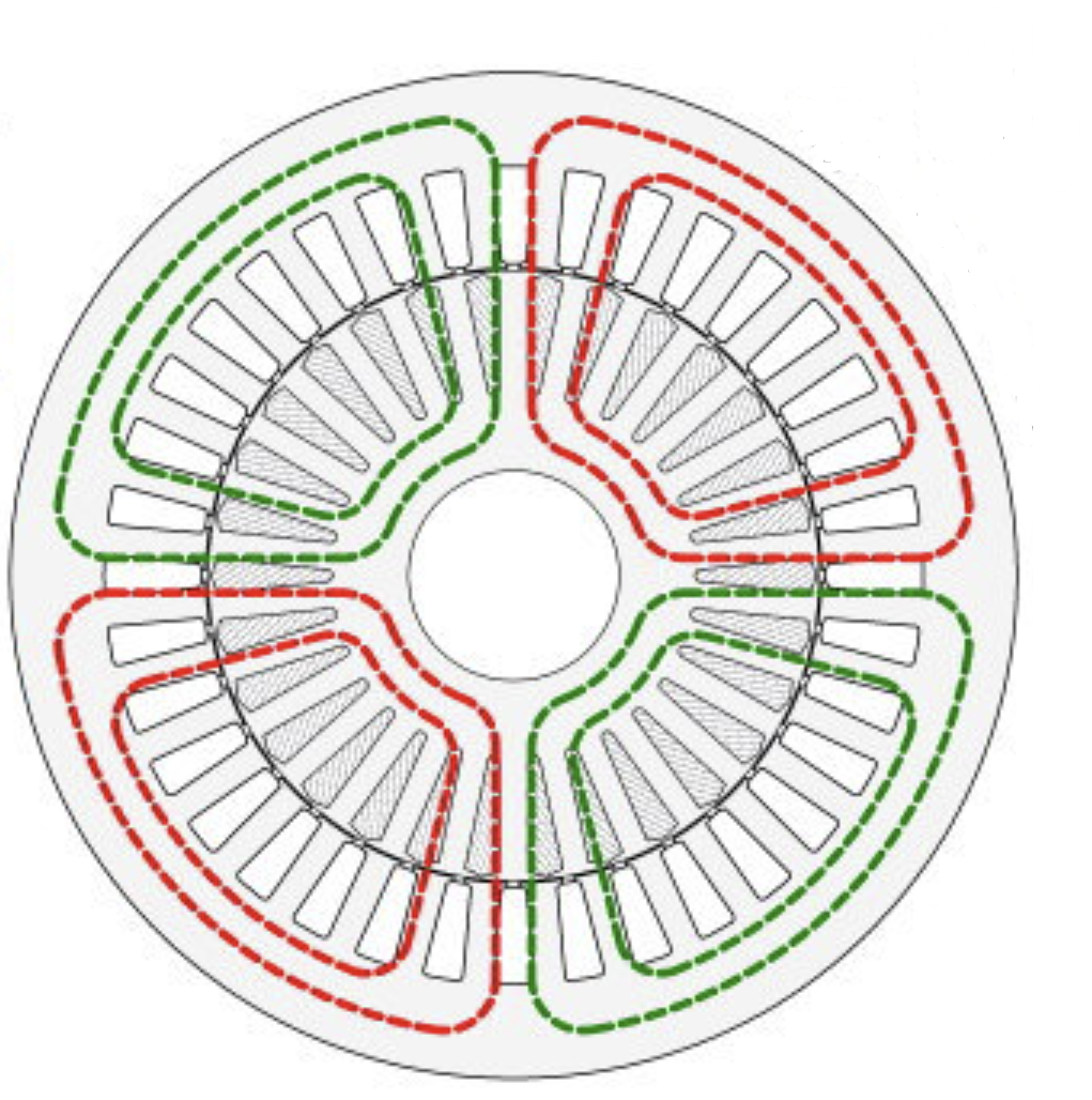
The source describes IGBT-based single-phase H-bridges with floating DC capacitors between the utility grid and each phase of a standard 5 hp, 60 Hz, 230/460 V induction motor.
Maintain capacitor voltage and grid synchronization
Managing floating-capacitor energy was essential to avoid damaging voltage rise. A phase-locked loop synchronized the control with the grid-voltage angle.
Model and implement the controller
The described process combined MATLAB/Simulink system modeling with deployment to a dSPACE prototype controller. The source reports motor soft starting and the ability to obtain a leading power factor at the point of common coupling.
Reported disturbance response, with limits
The document also reports ride-through of voltage sags and swells without tripping in the demonstrated setup. Sag/swell depth, duration and a controlled comparison with conventional drives are not provided, so a universal operating-range advantage is not claimed.
Explore the source material.
Video link supplied in the company document; not independently reviewed for technical performance.
Project description and outcomes are self-reported in the supplied company document. Linked video material is provided as a source reference, not independent verification or a customer endorsement.
Connected expertise.

Hardware-in-the-loop test setup · supplied document
From offline simulation to real-time HIL.
Develop propulsion-system models in MATLAB/Simulink and bring machine and controller behavior into real-time testing.
Explore →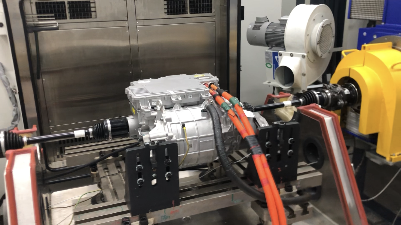
Powertrain dynamometer test bench · supplied document
Prototype testing with a clear measurement plan.
Support motor test setup, instrumentation and experiments from small drone propulsion machines to larger traction systems.
Explore →Bring us your challenge.
Start with your application, constraints and the decision you need to make.